Introduction
In the design and control of human assistive robots, human body parameters must be carefully considered to ensure effective assistance and seamless interaction. From a design perspective, factors such as body segment dimensions, joint range of motion, and pressure distribution influence the robot's structural configuration and wearing part mechanisms. In control, real-time adaptation to individual biomechanics is essential for intuitive and comfortable assistance. Moreover, assistive robots themselves can serve as tools for human body parameter identification by leveraging onboard sensors, such as encoders, force sensors, and IMUs, to estimate limb dynamics, joint stiffness, or neuromuscular responses. By integrating adaptive control strategies, assistive robots can not only provide personalized assistance but also refine their models of the user's physical characteristics over time, enhancing both safety and performance.
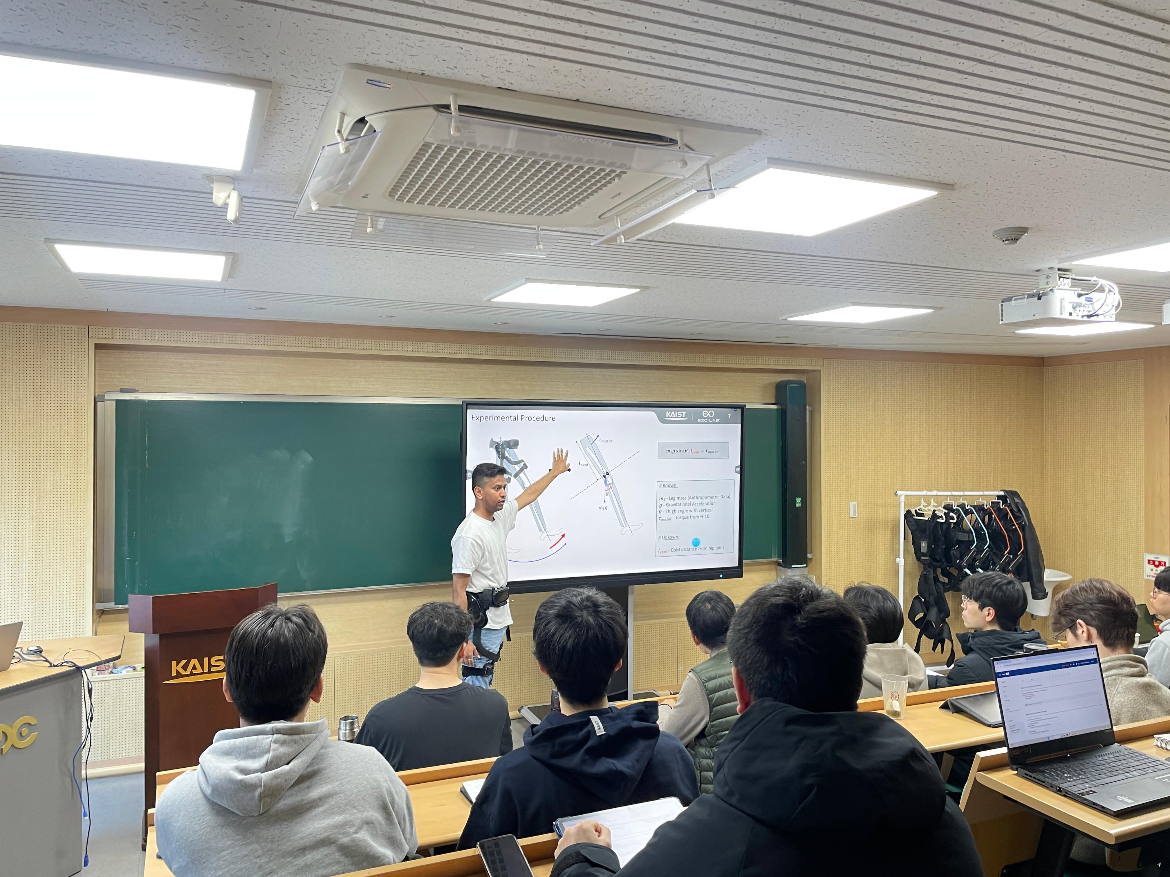
This demonstration presents the process of identifying human body parameters using H-10, a human assistive robot. The location of the leg's CoM (center of mass) is selected as the human body parameter to be identified, as it is crucial for the accurate dynamic modeling and control of the assistive robot.
Motivation: Why Identify Physical Parameters?
Physical parameters are critical for:
- Design of Human Assistive Robots:
- Assistance torque estimation for actuator selection
- Customized device design based on user-specific parameters
- Design of wearable parts with optimal pressure distribution
- Control of Human Assistive Robots:
- Precise state estimation using human dynamics models
- Real-time reference generation for balance control
- Trajectory generation considering individual physical parameters
Assistive robots can also be used as tools for parameter identification, leveraging their sensors and adaptive control to estimate user-specific biomechanical properties.
Experimental Procedure: Identification of Leg CoM
Experimental Setup and Data Collection
The experiment began with the human subject wearing the H-10 assistive robot, ensuring proper alignment of the robot's actuators with the human hip joints. The H-10 suit allows for precise torque application at the hip joint through its electric motors, controlled by the control module (CM) and motor driver (MD). Onboard sensors, including absolute encoders for joint angle measurement and current sensors for torque estimation, were used to collect real-time data.
The experimental protocol involved applying stepwise increases in current inputs to the motors, which translated to torque inputs at the hip joint. The torque applied by the motor is proportional to the current flowing through the motor, with a torque constant Nm/A:
Each current step was maintained for 5 seconds to ensure a static condition, minimizing dynamic effects. The joint angles were measured using the absolute encoders, and the data were logged by the CM. To further reduce the impact of transient responses, the average joint angle from the last 0.5 seconds of each 5-second step was used for analysis. This ensured the leg was in a steady-state position, where the applied torque balanced the gravitational torque exerted by the leg's mass.
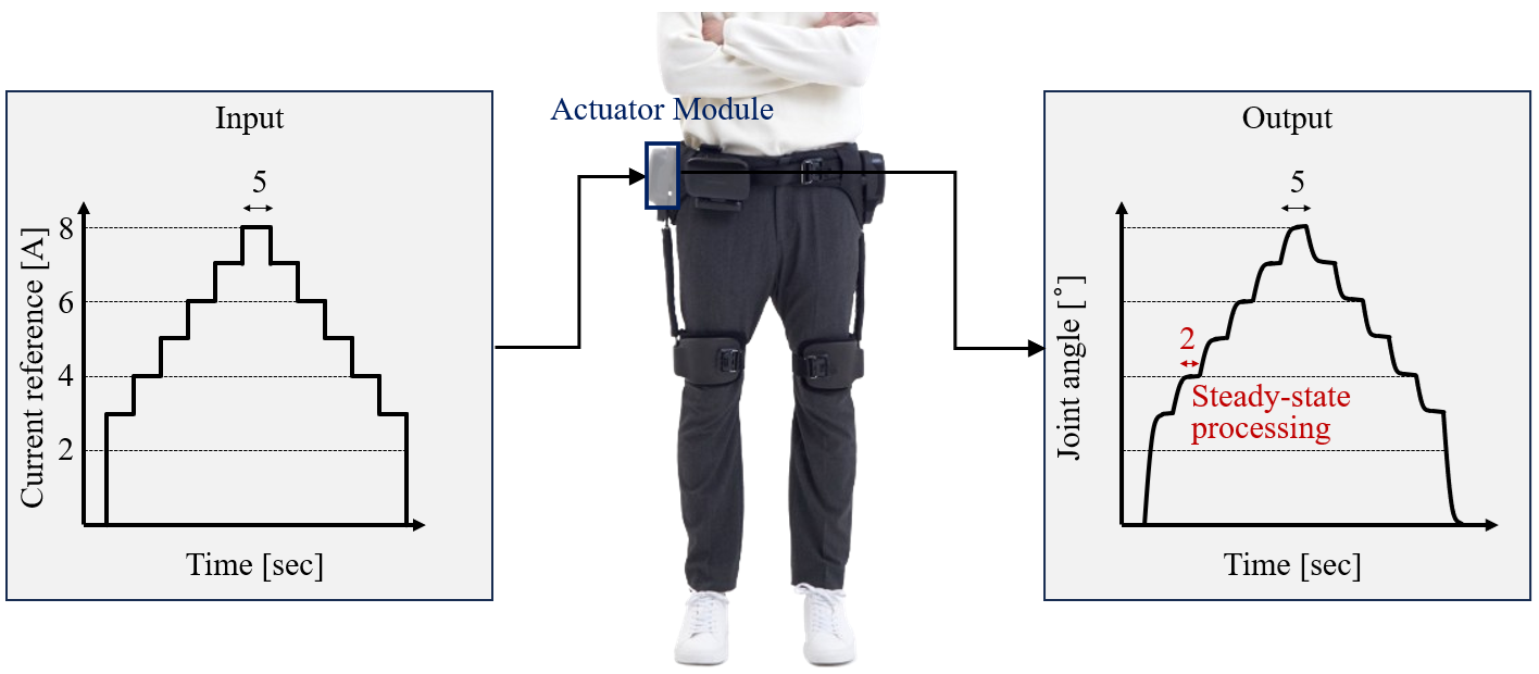
Input currents and estimated output joint angles of body parameter identification
During the experiment, the subject relaxed their leg muscles, allowing the H-10 suit to fully support the leg's weight. The leg was lifted to various angles by the suit, and the corresponding current inputs and joint angles were recorded. The data collected included the motor current (in amperes) and the hip joint angle (in degrees).
Data Processing and CoM Identification
The recorded data were processed offline to identify the CoM of the leg. The identification process relied on the principle of static equilibrium, where the torque applied by the H-10 suit's motor balances the gravitational torque due to the leg's weight. The gravitational torque about the hip joint is given by:
where:
- is the mass of the leg (kg)
- m/s is gravitational acceleration
- is the distance from the hip joint to the CoM of the leg (m)
- is the hip joint angle from the vertical (radians)
Since the experiment was conducted under static conditions, the applied torque equals the gravitational torque :
Substituting the expressions for and :
Solving for :
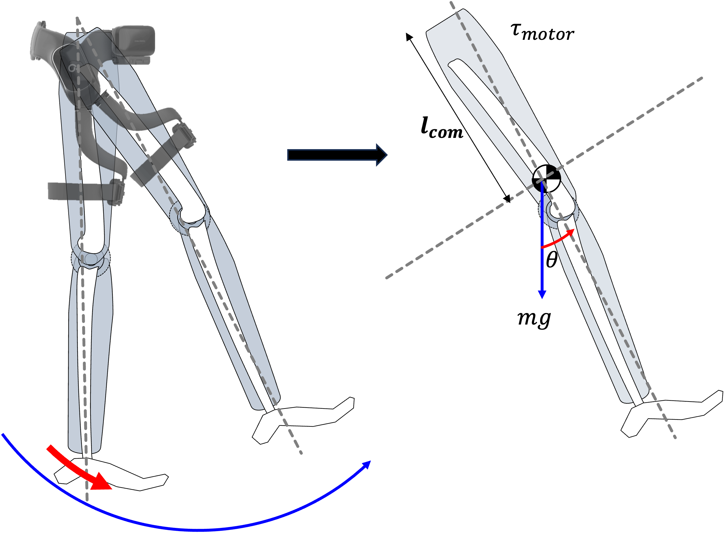
Illustration of the experimental procedure to identify the center of mass (CoM) of the leg
To apply this equation, the mass of the leg was estimated using anthropometric data. According to standard anthropometric studies (e.g., Drillis and Contini, 1966), the mass of one leg (including thigh, shank, and foot) is approximately 16.7% of the total body mass:
The recorded data provided pairs of current and joint angle for each step input. The angle (in degrees) was converted to radians for the sine calculation, and was computed for each data point using the equation above.
System Architecture and Data Flow
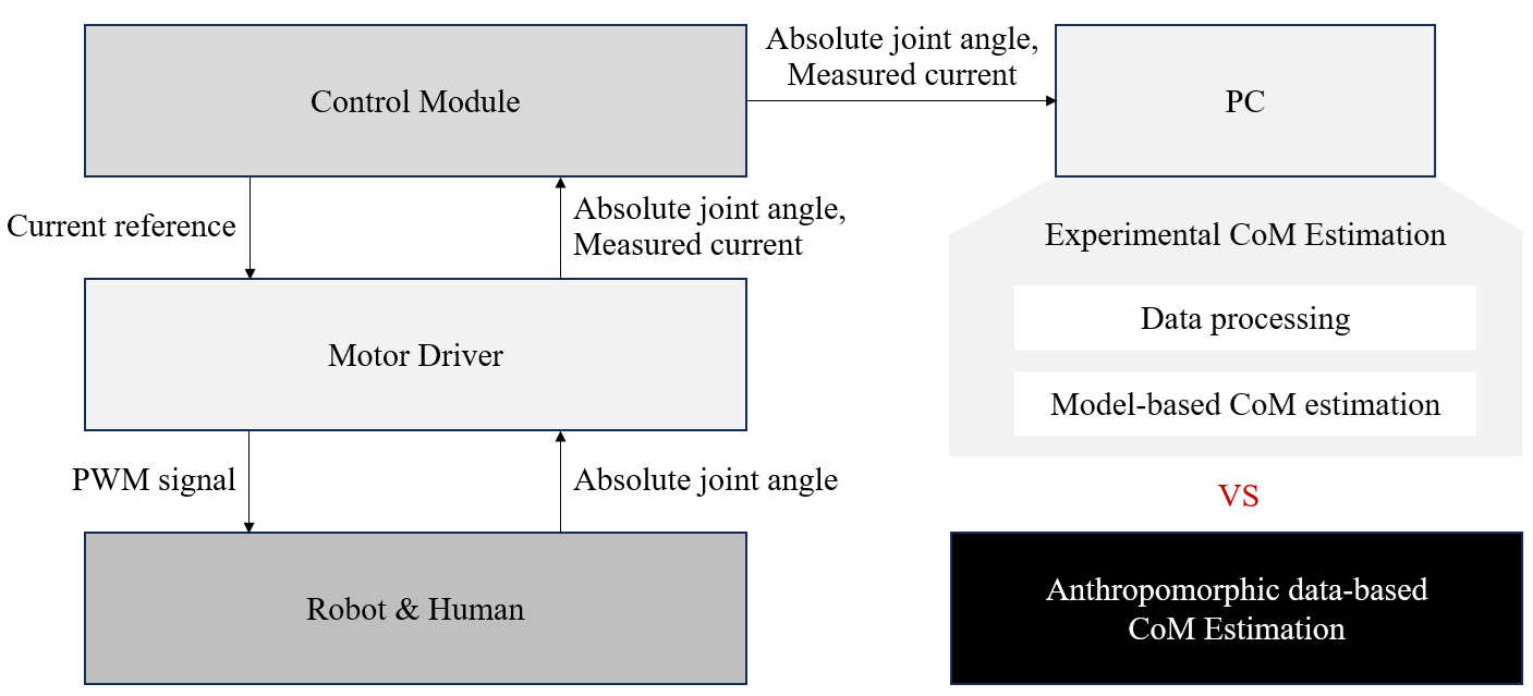
System architecture for experimental and anthropometric CoM estimation
Comparison with Anthropometric Estimates
To validate the experimentally identified , the result was compared with an anthropometric estimate of the leg's CoM location. The anthropometric calculation followed these steps:
- Leg Length Estimation:
- The total leg length (from hip joint to ankle) is approximately 53% of the total body height. For a subject with height m:
- CoM Location:
- The CoM of the leg is located at approximately 43.3% of the leg length from the hip joint (Drillis and Contini, 1966):
The experimentally identified was then compared with the anthropometric value of 0.3924 m to assess the accuracy of the identification process. Any discrepancies could be attributed to individual variations in body composition, experimental noise, or assumptions in the static model (e.g., neglecting muscle contributions).
Results and Discussion
A visual comparison of the experimentally identified with the anthropometric estimate can be made by plotting the results:
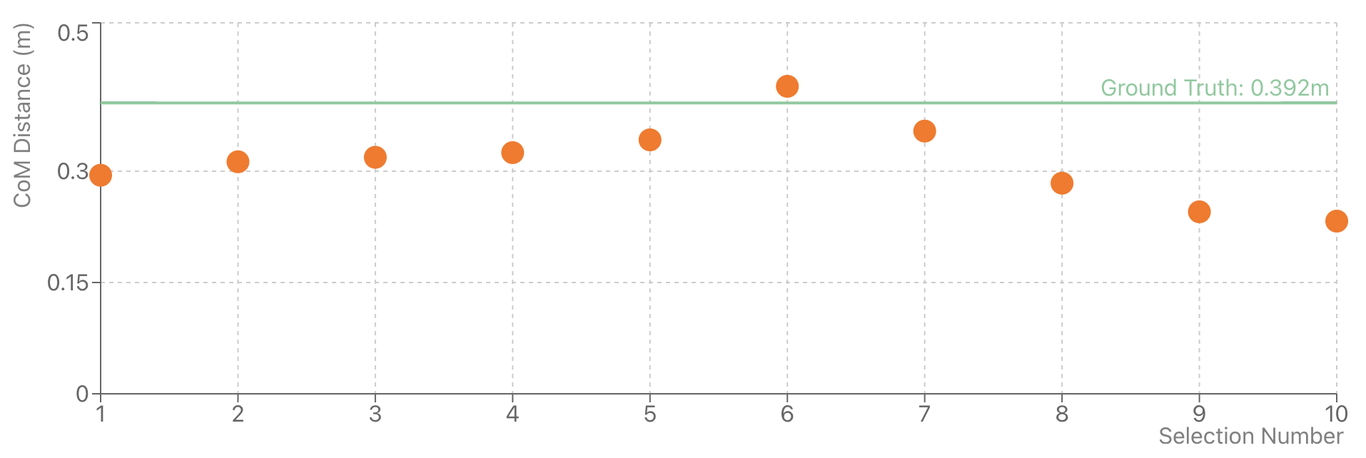
Comparison of experimentally identified CoM location with anthropometric estimate
From the graph, it can be observed that the experimentally identified CoM values exhibit some variation around the anthropometric estimate. Some values closely match the anthropometric method, while others deviate slightly. These discrepancies can be attributed to:
- Individual variations in body composition not accounted for in the anthropometric model
- Experimental noise due to sensor inaccuracies and measurement limitations
- Differences in posture, alignment, or interaction between the human subject and the assistive robot
Comparison Table:
| Method | CoM Location (m) | Notes |
|---|---|---|
| Anthropometric Table | 0.392 | Based on population averages, not subject-specific |
| Experimental (H-10) | Varies (e.g., 0.38–0.41) | Subject-specific, affected by experiment and sensor noise |
Both the anthropometric method and the experimental approach have their advantages and limitations:
- The anthropometric method provides a quick estimation based on established human body proportions. However, it assumes idealized human measurements and does not account for individual variations.
- The experimental method using H-10 can identify subject-specific parameters, making it more personalized. However, it may be influenced by sensor noise, alignment issues, and experimental uncertainties.
Sources of Error
- Experimental Method:
- Hardware-related errors (sensor noise, actuator inaccuracies)
- Human-induced errors (inconsistent movement, posture)
- Alignment issues between device and human body
- Anthropometric Method:
- Assumes idealized measurements, not accounting for individual differences
- Uses fixed percentages, which may not be universally accurate
- Does not account for real-time changes during dynamic activities
Conclusion
Identifying the physical parameters of body segments, especially the center of mass, is essential for effective design and control of assistive robots. The H-10 enables experimental, subject-specific estimation, offering advantages over traditional anthropometric methods. However, each approach has limitations. Combining real-time experimental data with anthropometric knowledge can lead to more robust and personalized assistive technologies.
This work was conducted at KAIST's ExoLab under the guidance of Prof. Kong.